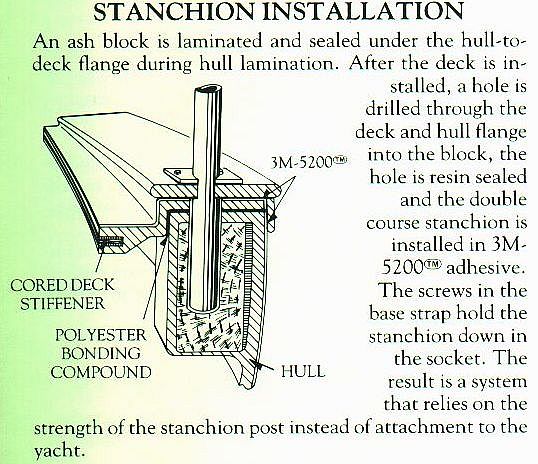
Repair and bedding of Irwin stanchions
Irwin owners can see the factory method of stanchion installation at www.irwinyachts.com
Go to the Engineering page to see.
The leaking, loose stanchions, or rotted blocks glassed into the hull to support the stanchion base can be repaired and sealed easily by inserting epoxy fairing compound into the hole with a putty knife or caulk gun, then insert a balsa dowel or carrot into the hole, the length of the stanchion tube base. The dowel or carrot should be less than one inch in diameter. The dowel or carrot will displace some of the epoxy mush and also force some into the cracks and crevices internally. It also gives direction for the one inch (or 1 ¼ for 65’s) drill that you will use after cured. Make sure your dowel or carrot is aligned, as your stanchion would be. Drill to the length of the stanchion base tube only. Mark your drill with tape to the length of your stanchion depth. The balsa or carrot is easily drilled out and gives drilling direction while honing out the epoxy to tightly fit your stanchion tube base again. Keep in mind that stanchions have various angles depending on their proximity on the toe rail. Stanchions on the forward section may not fit the aft deck sections due to the angle of the hull.
The self-tapping screws on the base plates of the stanchions do not support the stanchion. They only hold the stanchion down. Using larger self-tapping screws to fix a loose stanchion will only expand the problem and split your teak toe rail further and leak more. Use epoxy resin mixed with teak dust to fill cracks in teak and reamed out screw holes then re drill the holes for the self-tapping screws. . Properly Bed the stanchion and screws and you now have a non-leaking and solid stanchion. 5200 is not recommended as it is permanent. 4200 or equivalent will do.
Do not use epoxy resin as it may leak through to your interior and ruin other things. Access to the inner hull wood blocks from the inside of the boat is not easy and add many excess hours of work, if possible at all. Use epoxy mush or fairing compound.
Avoid using your stanchions as major hand holds to board the boat, or grasp them low to reduce the leverage that help cause the problems. Use your lower lifelines to attach fenders.
Keep in mind that all stanchions by any maker, of any design, on any brand boat, will leak eventually. All must be re-bedded periodically, just like windows, hatches and ports.
Hey Gene, > I found a real slick way to remove the stanchions that were bedded with > 5200. Get a welding glove and a propane torch, carefully and slowly heat the > stanchion above the flange, they don't have to get overly hot, just too hot > to the touch, with the fasteners out, the 5200 releases very easily! I just > put a steady light pull upwards on the stanchion while heating, this works > on any piece of metal that is bedded with 5200. Don’t need to heat to the > color change of the surface of the metal at all, that is why the propane > torch is ideal. > This is a good tip. > Tom Yarbrough > Citation 31
An earlier report from a world cruiser on an Irwin 54
Dear Sir, after numerous bad experiences with the Irwin stanchions, I can finally claim to have the perfect recipe to get them right. All is based on real life experience! The problem starts with the particular construction; Mr. Irwin is very proud of this, and gives an extensive description with drawing in one of his brochures. This construction is as follows.
Each (hollow) stanchion has an approximately 120mm extension that goes through cap rail, deck-hull joint and a wooden supporting block underneath, which together act as a shaft to carry side loads. On top of the cap rail sits a welded plate with two screws (also through the deck-hull joint) to hold the stanchion in place, and acts as the primary water barrier. This is where it goes wrong!
In summer 2000 in our marina our neighbor (a Moody45) missed his berth in heavy side winds and came across our starboard bow (which was sticking out 5m): result is slightly deformed pulpit, and the two forward stanchions. With a local specialist this was repaired in the usual way: straitening the affected parts and mounting with Sika. The result looked OK. However, within a year leaking to the interior started, especially in heavy weather. The leaking became progressively worse, and damaged the interior panels of the forwards cabin and bunk.
In Trinidad the pulpit was taken off to straighten more precisely and add some reinforcement and support for the am genoa pole. The steelwork alone cost 800US; maybe I was ripped off, but I could not get a better price. In order to match the screw holes precisely (you don't want to have side forces on the Sika seal, fitting had to be done 3x, and finally an exact template to be made to prepare everything in the workshop. Also the 2 stanchions were remounted with Sika.
In Chaguaramas I met Marcus, a professional boat builder, (refer to the reprint of X-Ray chain plates. Marcos was hardly a pro boat builder and Elizabeth Ann, the Irwin 52 he owned was trashed and even had a wood mast step when viewed in Florida a year later) who had just bought an older Irwin for refurbishing. He knew the Irwin's inside out (not really), and explained me many of the potential problems, like mast support, chain plates and stanchion leaking. He came over to our much newer boat (it is in fact one of the last 20 ones Irwin has built), and was pleased to see that many of the older problems were solved. Mast support is a solid construction now (Not True), and the chain plate is a one piece construction (Not True). He still had a welded connection for the intermediates, and refused to sail before X-Ray was done: a sister ship of his had lost the mast due to chain plate failure, and he knew of at least one other occasion as well. (Never a reported failure of internal chain plates, other than cracks above the pin connecting the turnbuckle) Beware of Experts tales of rumors.
Pity enough the stanchion problem was exactly the same, he showed and explained me the construction (see above), and gave me the final solution to tackle the problem. We went off to the Pacific, and not to our surprise the two bad ones started leaking again. Worse, careful investigation showed evidence that many other might also have started leaking. (Refer to the proper Repair of Stanchions and re-bedding document). The reason is now clear: the strong point in the construction is the deck-hull joint, which acts as the pivot point on side loads. The much weaker cap rail and the supporting block underneath get deformed, so the stanchion can move. This gives shear forces on the top seal and screws, and Sika can withstand almost any force but not shear force! The top seal starts to leak. The bottom seal is trickier. It's almost impossible to get enough sealant all around at mounting in the first place, and when this starts leaking the water runs directly from the lifeline holes into the boat! (These holes are a pressed-in tubing, not welded, with very tiny but fatal gaps). And side forces we got enough in Chaguaramas: people fending off their boat by pushing the stanchions, or hanging on them whilst climbing out of the dingy.
Now we know the reason the solution is also clear: close the bottom of the tube to avoid 'raining in', embed the lower 90% in a perfect epoxy casting to avoid side movement, and make a perfect top seal that still can withstand slight elastic side movement without shearing off (min. thickness 3 mm to absorb stress).Other solutions, like boring up holes and totally embedding in Sika will give too much side movement, and using solid stanchions will give unrepair able damage when really hit.
In Tahiti (summer 2003) we find a local woodworker with Epoxy and Sika experience, and we start on a bad forward sb. stanchion.
- We dismount and clean everything perfectly (incl. screws and screw holes, in order to get Sika in not only on top).
- We close the stanchion with a dowel and epoxy. We use some excess epoxy to seal the lifeline holes from inside.
- The 'shaft' in the lower support block shows some cracks and gaps, and is sealed with epoxy paste.
- Now the stanchion does not fit anymore, the shaft need to be drilled out at 1" again.
- Because there is more epoxy on one side, the drill runs side wards, and the angle is wrong.
- We redo the work, stanchion angle is now reasonable, but still not correct.
- Everything is masked, including an overflow device for the excess epoxy.
- All surfaces are primed (205, 290DC, 210T) according Sika handbook, Sika 291 is applied on cap rail and top part of stanchion shaft (we need a proper Sika bond on both sides before the epoxy flows over). The 3mmdistance pieces are put in place (in this stage 4 hands are needed).
- Pre-mixed epoxy is poured into the shaft, we are surprised about the amount needed.
- The stanchion is quickly inserted, some epoxy flows over the collection device and soils the deck.
- The screws are inserted, and cleaning up can start, curing of Sika in contact with epoxy is unbelievable fast, so a smooth finishing of the Sika proves difficult.
- Next day we can make a smooth cosmetic finish. Apart from the angle it looks like a good job.
As we decide to review the whole procedure (esp. the angle problem which cannot be corrected without starting all over), the next day we retrieve the cockpit cushions from the fore peak to take some rest. The last cushion is glued to the wall, the epoxy has been running through along the same path where the water had been running previously. Apparently there is more to review! (Again, refer to the proper Repair and re-bedding of stanchions document)
Much later we had to strip the whole panel and re-varnish. A matching cushion material could not be found, and all cushions had to be newly covered..
To test the integrity of the shaft, filling with liquid is the only solution: when it stays level for a few minutes it's ok, if not the shaft has to be repaired. The 'punishment' when epoxy runs though is too severe! The most save liquid is water, but this has an unrealistic drying time. Alcohol is a workable compromise, however also needs a day drying out. A solution for the angle problem has not been found, except being extremely careful at drilling. Two persons are a required to see both angles.
In Tahiti ALL stanchions have been redone according this procedure, and also the push pit (without the epoxy trick). The result was remarkable: not any leakage anymore till today. In Australia also all port lights have been done with the same precision, and also the hatch cover. Our Indian Ocean crossing was the worst ever (8 days more under than above water), without any drop inside. I don't see many leak free boats along the road, but I want to keep it that way.
The repair must be done according this specification, with the same care and precision. Compromises will certainly be proposed, but are without testing not acceptable and this is too time consuming. This method works, and is based on real life experience.
Time required for ONE stanchion: 1hr - removal (might be difficult!) and painstakingly cleaning all surfaces, liquid test. 1hr - repairing and drilling the shaft (only if liquid test fails, 50% chance) 1hr - masking and priming all surfaces (some idle drying time is unavoidable) 1hr - final assembly and cleaning up, masking and finishing the next day.
Note: working on 2 stanchions simultaneous is hopeless with curing time of primers, mixed epoxy, and the skin forming time of Sika. Note: for part of the work 4 hands and 4 eyes are needed (master and slave). I would love to help, but will only supervise: I was 3 days in hospital as a result of epoxy allergy.
Average time per stanchion 3.5 hrs, partly with 2 people, say 5 hrs total. For 2 gates (identical) and 2 stanchions we have thus 20 hrs, I can't help it.
For the push pit it is easier, as there are no sockets. However we still talk about 5 legs with 4 screws plus 2 support legs with 2 screws, totaling 24 leak free screws through deck-hull joint.
Time required for push pit:
4hrs: remove settee, cabling, and push pit. Thoroughly clean all surfaces and screw holes. 2hrs: fitting and re shaping till ALL 24 screw holes match the existing holes without side forces as Sika does not survive shear force over time.
4hrs: masking, priming, Sika, mounting push pit, fishing and cleaning, cabling, and then settee.
Note: for much of the work 2 man are required, the thing is too big to handle alone. Note: for mounting 3 man are required to apply Sika from both sides, hold in place and insert screws and start finishing from both sides. Even with 291LOT skin forming starts in 20min, by which time all 7 seals must be in place.
Note: time assumes new (identical) screws, as cleaning up old screws is too time consuming.
Total time 10hrs, mostly with 2 persons, say 16hrs.
Materials required: -general cleaning liquids -bottle Sika cleaner 205 -bottle Sika metal primer 210T -bottle Sika wood primer 290DC -4 cartridges Sika 291 LOT brown -epoxy paste -epoxy liquid -several sizes identical threaded screws
Once again, we have been through all these jobs before, and I insist to apply the same standard, nothing more and nothing less.
With kind regards, Nick van Erk, Sterling, Irwin 54.
Here is the general method one owner uses for re-bedding.
See Practical Sailor April 1st, 2005 and November 15th, 2005 issue for testing on caulks. I like BoatLife Life Caulk, which is a polysulfide, but I think it may yellow upon sunlight exposure. If you use 3M 4200 get the 4200UV. Many of the sealants will chemically attack plastics, so read the labels first if they will touch a port light.
Re-bedding Procedure:
- Purchase neoprene rubber washers from the specialty hardware section of your local home improvement store to act as spacers for the compound.
- Clean the old compound off of the deck and the fitting. To remove silicone caulk, wipe area with one of the following compounds or see GE Silicone web site: Plastics: Isopropyl alcohol Fiberglass or metal: mineral spirits, WD-40, xylene Concrete, slate: Dicone NC15 Gel (petroleum distillate, detergent, sulfonic acid) from Prosco Other: Amtex -CCR Silicone Remover at www.amtexchemical.com
- Silicone Be-gone from DAP
- If there is any indication of rot of the deck core, remove the rot and fill with low viscosity epoxy (Git-Rot or similar products from West Systems)
- Tape the area with blue masking tape extending 3+" outside the area of the hardware
- Place the hardware over the tape, trace with a ball point pen, and cut out with a utility knife and remove tape in the area of the hardware
- Tape the sides of the hardware and cut even with the bottom of the hardware
- Apply sealant to the deck and hardware. Use a flexible sealant like 3M101 3M 4200UV, LifeCaulk or one of the SikaFlex products
- Place fasteners through fitting followed by the neoprene washer, through deck and backing plate, backing washer and then attach nuts. The hardware will bottom out on the neoprene washer. Use a backing plate of aluminum or stainless steel of 1/8" for light loads or 3/8" for heavy loads.
- Don't over tighten until the sealant has cured. Then remove screws, coat with more sealant, and replace.
- Clean up the excess sealant with a square edged tongue depressor. Wipe any remaining sealant off with a paper towel with a little solvent on it. Now peel away the masking tape to clean up.
- After curing, tighten the nut at the backing plate while holding the bolt steady. Tightening the bolt will shear the sealant and ruin the repair. If necessary to tighten screws or bolts, remove them, clean and coat with more sealant, replace and tighten.
Here are two alternative solutions for the chain plate covers which may be more permanent although I have not tried them yet myself.
Rubber Gasket System Cut a piece of 1/8" thick butyl or neoprene rubber sized for the cover and cut a slot slightly smaller than the chain plate. Place over the chain plate and down to the deck. Place some small caulk on the screws and tighten down.
An alternate system uses an O-ring sized slightly smaller in ID than the circumference of the chain plate. Place this around the chain plate. Fill the cavity with Dolphinite 2005 push the cover plate over the chain plate squeezing the O-ring so it seals the gap between the chain plate and the cover and screw the cover down.
Boot System Cast an epoxy collar about 1" high surrounding the chain plate or cut an oval shaped ring 1" high from composite stock, plastic stock, or teak and epoxy to the deck around the chain plate. Then form a boot from vinyl from the bottom stud of the turnbuckle to this collar. A simple one can be made from duct tape.
Regards, Harry Anderson
SAILHAPPY@COMCAST.NET
SAILHAPPY.COM - site in construction - helpful manuals, check lists, procedures for sailors, |